A few years ago, I re-examined a lot of design elements of the SYclotron, which topologically is a cross-coupled FET-tube hybrid differential amplifier, the tubes being the voltage amplifiers and the FETs configured as source followers. While keeping that same basic topology, I was able to optimize performance for use as a preamplifier (see the Equal Opportunity Preamp articles in Linear Audio volume 7 and volume 8). The circuits feature good common-mode and supply rejection, and excellent linearity and bandwidth, with notable low input capacitance (the bugaboo of most tube and FET phono stages). I mentioned in passing the possibility of using it for a power amp input or driver stage, which would require greater voltage swings but is less critical regarding noise level.
Here’s my first pass at it (the schematic is a bit simplified- use bypasses at supply rails, and you’ll need heater power). To get more voltage, the tube has been changed out to an ECC81/12AT7, which can take a lot of volts on the plate (comparatively). Because the noise floor of a power amp doesn’t need to be as low as that for a phono stage or mike preamp, I subbed cheap J271 FETs for the expensive and rarer LSJ74s used in the Equal Opportunity. The current source plate loads are set for 2mA, a good current for the 12AT7s to run linearly- the resistor values I have for biasing the CCS will need to be selected for your particular DN2540 MOSFETs).
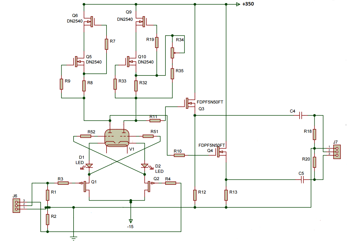
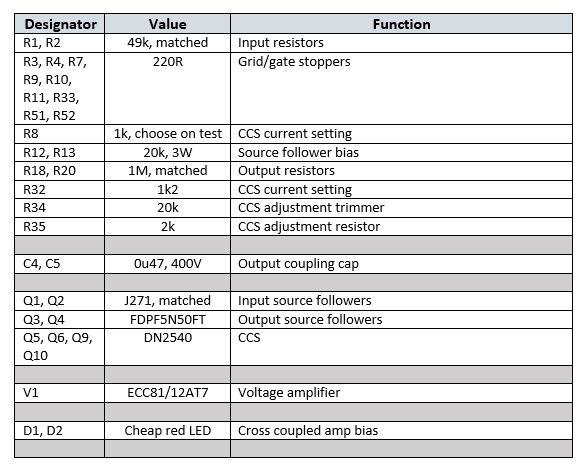
Note that because I wanted to use the Equal Opportunity PCBs for the initial tests, the topology isn’t optimal for a power amp driver stage- ideally, if this were driving output tubes, you’d put RC coupling between the tube plates and the FDPF5N50FT gates, returning the source resistor to a negative rail and direct coupling the sources to the output tubes’ grids. Still the swing and distortion performance will not be significantly different than my proof-of-concept setup. The component values in my tests are shown below:
For testing, I drove this circuit with a balanced signal; for a single-ended input, an input transformer like a Jensen JT11P-1 will work beautifully and, as a bonus, provide galvanic isolation. R34 was adjusted to null out even order distortion. There’s a trick to increase CMR which will be implemented in the next version of this circuit (basically, tie the junction of the two input resistors to ground through a large resistor, like 1M, instead of directly to ground as shown here).
The results were gratifying: gain was 52.2 (34.4 dB). Frequency response was flat beyond the measurement limit of the APx515 analyzer. At 21V out (enough to drive EL84 to clipping), the only harmonic above the noise floor was the 3rd, at -85dB (0.006%). At 65V out (enough to drive EL34, 6550, 6L6, KT88), 3rd measured -62dB (0.08%). At 84V out, enough to drive 6L6 into AB2, 3rd harmonic was at -55dB (0.18%) and the 5th was just becoming visible.
Note that there was no attempt to vary operating points to optimize swing and distortion, but be assured, at some point there will be. In the meantime, this initial try showed great promise,
You mentioned the EO output stage as suitable for this, and seeing some initial trials is very exciting! Thanks for using J271s instead of J74s, always good to have a guru’s blessing on audio worthy parts. 🙂
Looking forward to your followup where the RC topology is tried!
Stu
Just a thought, but another option is taking the output from the mu-output of the CCCS, thus giving both low output impedance and eliminating the source follower stage.
There’s always tradeoffs- when you do that, you reduce the impedance of the CCS, but you indeed save a couple of parts. Is that significant? It can be in some circumstances, but since the parts are cheap, I figure, meh, I’ll play it safe.
Very Nice.
A pity about them output coupling capacitors, though ….
Maybe some DC servo modification, some speaker protection circuit ==> and capacitorless ?
Cheers,
Ziggy