A common engineering challenge in home audio is the addition of an active subwoofer system to speakers that have limited bass extension. Generally, this is done by taking the preamp output through a set of complementary filters which give the desired high-pass and low-pass response. The advantage compared to old fashioned passive (speaker-level) filters is size, cost, and performance. The traditional downside (double the number of amplifiers) is no longer much of an issue, what with inexpensive high performance amplification available in chip form. The economic calculus has shifted so far that it is now difficult to find commercial subwoofers lacking built in amplification and filtering; likewise, nearly every home theater and computer sound system now has separate bass and upper channel outputs.
For high performance audio, this is insufficient. Crossovers must be considered in light of the acoustic response of the speakers/room in order to hit the target transfer function. That is… unlikely to have been done by the anonymous design crew for the third world factory supplying the Big Name Brand on sale at Best Buy. Even conscientious engineers at reputable companies making separate electronic crossovers are unable to do that since they’re designing for an audience which could have any of a Vast number of potential speaker-subwoofer combinations, all of which will have different requirements. And the low-bid opamps prevalent in the usual soi-disant home theater receivers will challenge the notion that modern circuits are by and large audibly transparent.
What I will do here is to show how my crossover system was designed and built, putting in my usual pedagogical blather. But the design basics are here, and you should be able to adapt this to your needs if you can plug in your own numbers and work the same equations.
My Design Targets
In my own case, I’ve owned a variety of small sealed-box speakers over the years, all of which needed lower bass augmentation. The situation was similar for the M3.3 biamping project. It comes down to where the speaker rolls off (the fo) and how gradually it does so (the Q).
A convenient and useful target crossover is the Linkwitz-Riley 4th order. The slope is steep enough to severely limit the excursion of the woofer being high-passed, and of the common crossover functions, it is the least sensitive to relative driver acoustic center. The lobing behavior is also quite benign. See Vance Dickason’s “Loudspeaker Design Cookbook” for details. The nice thing is that most small speakers are sealed boxes (or can be made so), so the acoustic response is second order. If we combine a second order electronic filter ahead of the power amp feeding the satellite, we can, by choice of filter damping and/or speaker box modification, synthesize an overall L-R 4th order acoustic response.
Most small speakers have a highish Q alignment. This puts a bump in the frequency response just before rolloff, subjectively “filling in” for the missing bass. The bump is the number one cause of poor subwoofer-main speaker integration when off the shelf “universal” crossovers are used.
There are a few ways to smooth out the bump and integrate the bass properly. One way is to actually modify the satellites to reduce the bass Q. This can be as simple as altering the stuffing or introducing a resistive port (the notorious “Variovent” for example). The other is to accept the speaker’s Q as-is, then plan the electronic crossover’s damping to be relatively low. For example, a small speaker with a corner frequency of 90 Hz and a Q of 1.0 can be mated with a second order filter at 90 Hz with a Q of 0.5.
Not that any of this is ever done. Generally, the audiophile buys an off-the-shelf electronic crossover and prays. And most commercial electronic crossovers are sad affairs, stuffed with low-bid components, and set up for drivers which probably don’t exist.
What makes things worse is the near-universal adoption of one of two topologies: the Sallen-Key and State Variable filter systems. This is one instance, I believe, where conventional engineering thought is very much down the wrong path.

(Above) State Variable Filter
(Below) Sallen-Key Filter, 110Hz
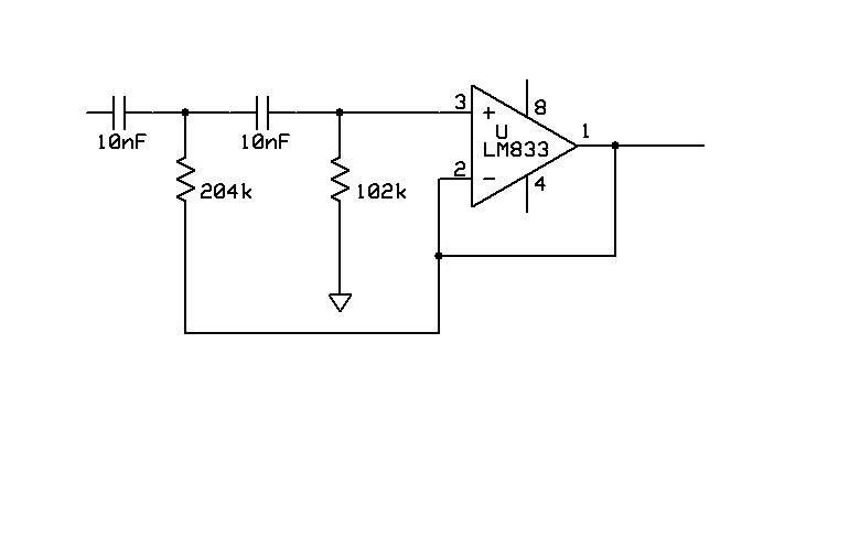
Let us take up the State Variable Filter first. The SVF is a three stage affair, all stages being high gain, and a combination of positive and negative feedback. The requirements for all stages to be high gain, high bandwidth, and low distortion means that a good implementation will be complex and expensive- the usual op-amp stuff won’t cut it here except in cheap equipment. And cheap equipment will certainly take advantage of two features of the SVF: the ease of tuning the crossover frequencies and damping, and the ability to extract symmetrical bass, mid, and treble outputs from the same three opamps- the high pass comes from the output of the first opamp, the band pass from the second, and the indicated output is low pass. Separate filter blocks can be built for low pass, band pass, and high pass if different frequencies and damping are needed (nearly always the case for real-world speakers and never done by the cheap crossovers). But now we’re talking about a minimum of six high gain, high bandwidth, low distortion amps for a two way system… tilt! And of course the signal will have to pass through a minimum of three gain blocks per channel, which is not part of the recipe for fine sonics.
The Sallen-Key is used in most crossover setups with any pretension to quality. It’s a single amp, run at unity gain, though often accompanied by one or more auxilliary buffers. Getting a buffer to be low distortion and wideband is a much lesser challenge than the high gain stages needed for the SVF, so a conscientious manufacturer will no doubt splurge a bit. And the results are often acceptable. But there is an Achilles’ Heel, and that is relatively high distortion because of the positive feedback. In a very clever paper, Peter Billam (JAES v26 n6, p426, 1978) showed that the positive feedback “aggravated” the distortion through the crossover region, and by a surprisingly high amount. His measurements suggest an 80-fold increase in distortion at the corner frequency.
That is not, for me, a great selling point for this topology. Is there a Third Way?