(see notes at the end of this article for latest updates)
Just what the world needs, yet another push-pull EL84 amplifier.
Well, I’ll try to justify its existence by saying that it takes into account some design goals not fully addressed in earlier work. And at the same time, I wanted to keep it simple enough for a novice builder. The logic of each design choice will be, I’m afraid, explained in excruciating detail; I like to think of these projects as teaching tools rather than rote recipes. And the reward at the end is some lovely sounds.
What is your name?
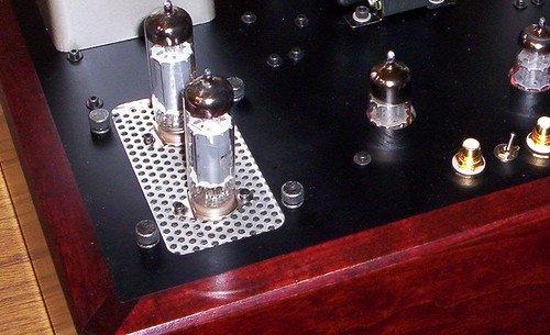
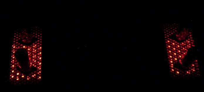
As I fired up the prototype, a red glow suffused the room, a gaudy, cheerfully sleazy illumination. Well, not surprising, considering the near-hundred red LEDs adorning the chassis. I immediately thought of some lost nights long ago in Amsterdam, so inevitably, I dubbed this amplifier “The Red Light District.” My friends with marketing savvy tell me that Japanese names are “in” for tube amps, so call it the “Yoshiwara” if that’s more your orientation.
What is your quest?
Much of a design can be immediately determined if we are explicit about the design goals. The more explicit the goals, the clearer the choices. I’ll outline what my design goals are:
- Power: 15W, scalable to higher power- this is good enough to drive most high efficiency speakers to deafening levels, or on the delicate end, run a pair of Quads.
- Reasonable efficiency- I am willing to sacrifice something to get good sound, but cannot afford the electric bills that come from running inefficient amps and having to cool the room. As responsible habitants of this planet, we have to consider how we use resources.
- Reasonable linearity and source impedance- – I do NOT subscribe to the school of power amp as signal processor or effects box. Basic linearity requires good distortion measurements. At the same time, I do not make a fetish of the number of zeros behind the THD decimal point.
- Excellent overload recovery- I think that this is the number one source of audible differences between otherwise-good-measuring amps.
- Stability into reactive loads- I own electrostatic speakers. And LS3/5As appear here from time to time.
- Constructed from easily available and non-exotic parts- This amp is perfectly buildable by anyone with intermediate construction skills and a few weekends to spare at a cost of a couple hundred bucks.
- Sensitivity of 2V RMS input for full power output at the 8 ohm terminal. For a 15-18W amp, this translates to a gain of roughly 6. Modern signal sources are at a 2V level, so we do not need to require any gain from a preamp. In fact, this project can easily be built as an integrated amp by adding a volume control and input switch.
- Low noise, 100dB down from full power- This amp is likely to be used with fairly efficient speakers and ought not to hum, hiss, or otherwise get in the way.
- Able to easily be reconfigured to a current source mode- Mills and Hawksford showed the potential advantages of current source amplifiers driving speakers. This concept was reified by Nelson Pass’s First Watt. We can’t let the solid state guys have all the fun.
What is your favorite color?
First, we will use a push-pull output stage. Single-ended stages have their attractions, but accurate (in the sense of the output replicating the input) they are not, at least not without enormous cost. Although proponents make much of the reasonably low distortion figures at low powers (say, 1W), this begs the question in two ways: the distortion at low powers is STILL greater than for a well-designed push-pull amp, and more importantly, we are using this amplifier for MUSIC. Yes, the 1W distortion of a typical SE amp might be fine, but do we want the leading edge of plucked guitar string (for example), which could easily be 10-20dB above average level, to be spraying distortion around? The defense of single ended circuits is reminiscent of the old set-up line, “She’s got a great personality and a wonderful dancer. Life of the party!”
The power requirements can be handled by a variety of good tubes.
The traditional answer is EL84/6BQ5. These tubes have the advantages of high gain, low B+ requirements, easy availability, low cost, low distortion, and excellent track record. OK, good enough, but I will not argue with someone who uncovers a cache of NOS 6973 or 6CZ5. I have not, so it’s EL84 for me. The high sensitivity will turn out to be very useful in achieving some of our other design goals.
One lovely advantage of EL84s is the thoroughness of the documentation. The Mullard spec sheets are a veritable how-to for nearly any design that one can evince. Being the lazy sort, this tips the scales even more heavily for me- I always like it when someone has already done the dirty work.
We next need to consider the topology (triode, pentode, ultralinear, or something exotic).
It is entirely possible to use any of these topologies and make an excellent amplifier. This amp will use pentodes. This statement is bound to cause consternation and I can almost hear the door slams of many people’s minds closing. The choice seems arbitrary now, but as will be seen, it will allow us some design options which will maximize the dynamic performance, linearity, and kindness to the ears. The reality is that, used wisely, pentodes can have the low distortion, low source impedance, excellent load tolerance, and good sound of well-wrought triode designs with a fraction of the complication and a multiple of the efficiency. And the Mullard documentation suggests that an 8k plate-to-plate load will be optimal. For my prototype, I used some transformers salvaged from a Dynaco SCA35, which are easily available new if you can’t find an old unit. One brand with which I’m familiar is “Dynaclone.” The Dynaco units worked very well, but I would not disagree with the decision to go a bit higher-end and use a more luxurious hunk of iron. I’ve built units with UTC LS54s and James with excellent results.
The next question is output stage biasing.
There are various schools of thought here, but whatever is chosen, we must keep in mind overload performance. It’s one thing for an amp to clip here and there for a few milliseconds, but if its bias shifts and the amp strangles for a second or two thereafter, it will be unlistenable except at very low levels. This so-called “blocking distortion” has been the Achilles heel of many an otherwise-competent design. Our choices here will have a profound effect on the amplifier’s overload recovery and its consequent sound (as opposed to typical measurements).
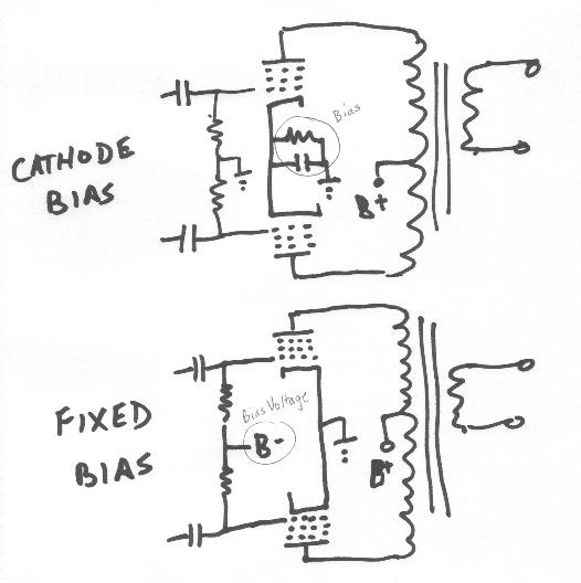
Cathode bias (also referred to as “automatic bias”) has the virtue of simplicity and safety: no runaway output tubes if a supply fails, at the cost of some efficiency and power. Cathode bias, however, is problematic from an overload point of view. Consider an output stage driven beyond its means for a few seconds (my goodness, those kettledrums were loud!). As the current rises, so does the bias from the cathode resistor/capacitor combination. Once the overload has passed, the bias remains high until such a time as the capacitor can discharge and return the cathode to its previous voltage. During that time (usually on the order of a half second), the amp suffers remarkable amounts of crossover distortion, and when it suffers, so do your ears. The time constant for that discharge then is forced to be a compromise between recovery time and bass response- the quicker the recovery, the higher the f3 of the output stage. Recovery time is usually the loser- blocking rears its ugly head.
One way out of this dilemma is to lose the bypass capacitor entirely and run the output stage in class A. No bypass is then needed on a common cathode resistor. And that’s a fine choice if 5 watts output is satisfactory. But it fails our design criteria- 5 watts will not light up a pair of Quads, and it somehow seems unfair to ask the output stage to dissipate 45 watts or so for such a measly return. Some enterprising souls will try a variant of this and use a current source to feed the output tubes’ cathode, effectively turning the output stage into a differential amp. Again this restricts us to Class A and has very uncertain overload characteristics- some current sources will react to a face-slap by screaming and throwing a fit. So whichever approach we take, making the RC or CCS cathode biased output stage recovery from overload a clean and uneventful one extracts a cruel cost.
Fixed bias (a confusing name for a topology that usually includes an adjustment pot!) has the advantage of extracting the greatest power with the highest efficiency. But it carries a large parts count, it will allow the output stage to destroy itself if a bias supply fails or becomes disconnected, and it is susceptible to a very nasty clipping artifact, another variation of the dreaded blocking. This phenomenon occurs when the grid, driven past zero volts, picks up electrons which, upon the passing of the overload, take time to drain out through the coupling cap/grid leak resistor combination. In fact, it will take a couple of time constants to discharge, during which time the amp will be severely over-biased, causing some ugly crossover distortion. Presumably, the RC time constant is a long one to minimize phase shift in the bass, but that will mean that any clipping will cause the amp’s distortion to be painfully audible. As a side note, the automatic bias system does not avoid this problem, either. To add insult to injury, when the output tube is driven into grid current, its impedance drops precipitously, kneeing the driver stage in the groin.
The brute-force solution is to design a driver with a very low source impedance and a very high current-drive capability, typically a cathode follower. This is a fine solution and probably the preferred method for a “super amp,” but we’re trying to keep things simple. Our decision to run the output stage as a pentode will pay yet another dividend- it gives us a cheap and easy workaround to the grid current problem.
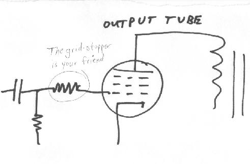
An old, nearly-forgotten method to limit grid current is the use of a grid-stopper resistor with a higher value than normal. The resistor now has a current-limiting function as well as its traditional use in suppressing oscillation. For example, if a 47k resistor is chosen, any grid current will be limited to a milliamp or two. This will limit any tendency of the output stage to block via the grid. The downside of this approach is the high frequency roll-off set between the grid resistor and the input capacitance. For a triode configuration of the output stage, the capacitance is high enough that the pole will be dangerously close to the top of the audio band, and certainly close enough to the output transformer’s high frequency limit to make stability problematic. A pentode, on the other hand, has a sufficiently low input capacitance that this pole can easily be placed a decade (or more) higher. So for the cost of two resistors, we can greatly improve overload recovery. Seems like a plan!
Now, with the grid blocking problem attended to, how do we deal with biasing? With much thought and many glasses of excellent Dutch beer, the proverbial light bulb came on. I had been doing some bench tests on various small-signal triode circuits using LED bias and had incorporated such a scheme into a prototype preamp with good results. Low dynamic impedance, fast overload recovery, good linearity… why not then use this in a power stage? It could solve the biasing issue and take care of half the overload problem at the same time.
…our beacon, which, I just remembered, is grail-shaped. It’s not the first time we’ve had this problem.
Let’s look at the practicalities. The required voltage from cathode to grid under typical EL84 operating conditions is roughly 10-11V, so conceivably a series string of six or seven red LEDs could work. Two problems immediately arise: the highish impedance of such a series string (if a red LED has a 4.5 ohm dynamic impedance, a series string of six LEDs will have a 27 ohm impedance, which is rather more than we would wish) and current requirements (at full tilt, a pair of EL84s will shoot 120mA or so out their cathodes and most normal red LEDs have a 30mA or so maximum current). The obvious stone to kill both of those birds is paralleling the series string with several other series strings. For example, a parallel combination of seven series strings of six LEDs each will have a dynamic impedance slightly lower than a single LED, i.e., something less than 5 ohms, a very reasonable value. And with the current divided seven ways, the LEDs will run at a safe and comfortable 15mA or so with the amp at full throttle.
The objection then arises that this will require a minimum of 42 LEDs per channel, if we use a single array for each pair of tubes. That means eighty four LEDs for a stereo amp. On review, that’s really not so bad- the LEDs put out nearly no heat and they are quite cheap. A local surplus outlet had a dozen varieties of red LEDs on sale for $3-6 per hundred, which makes this a far cheaper proposition than the power resistor plus bypass caps required for a cathode bias arrangement. And new LEDs are not very much more than that. Compare this with the cost of a negative bias supply or a cathode power resistor and associated audiophile-grade bypass cap…
Note the assumption of a common LED array for each pair of output tubes rather than individual arrays for each tube. This saves parts and at the same time delivers another nice gift- any small error signal due to LED nonlinearity is common-mode and will be suppressed by the common-mode rejection of the differential output stage. Again, one stone, two birds.
Hi Sy,
I’m going to build me one of these some day, but my first priority is a new preamp. After reading this and knowing that all things look like nails to a hammer I’m thinking of a 12b4a pre with a DN2540 20mA load biased at 18v with an LED array. I really want to try this. I’m thinking it will take something like a 11×6 array will do the trick. Is this a reasonable approach?
Hi Dennis, if you’re running 20mA, two strings in parallel should be fine. There, I saved you a dollar or two. 😉 Although I haven’t seen much of an issue with current hogging using LEDs out of the same lot, I’d still put a small (2 to 5 ohm or so, I usually use 4R7) resistor in series with each string to equalize currents, just in case.