To review, in Part 2, we considered a very basic transformer-coupled input, capacitor-coupled output unity-gain preamp. That circuit is, as it stands, an excellent performer. We do need to power it and to build it, so those circuits and options will be considered before we move on to some fancier variants. But this is a fine stopping-off place if you just want a good sounding, reliable, easy-to-build preamp.
In this part, I’ll cover the raw supply, the regulators, some construction notes, and a few words on parts choices. It’s a bit unfair to have you make decisions in the dark, so I’ll preview the next variation: I hate large capacitors, so I trade the large output cap for a small input cap, direct-coupled output, and servo to clean up the offset. And the last iteration will substitute a rather novel servo for the usual method, decoupling the servo even further from the signal. This will come, as usual, with a degree of trade-off… If the idea of wrapping op-amp circuits around your preamp gives you the willies, this first version ought to be your final destination.
Discipline
We need to power our circuit. To do so, we would ideally have a supply that gave us exactly the DC voltages we need with the effortless silence of a skilled servant. We have made things somewhat easy for Jeeves by perspicacious design choices: a cathode follower has excellent immunity to power line disturbances, the high impedance current source isolates the cathode from most of the noise or wobbliness remaining on the -12V rail after regulation, and the heaters can trivially be made blameless by wiring and grounding correctly. But the supply needs to be good enough to not be the limiting factor in distortion and to achieve low enough noise such that the preamp’s total signal to noise reaches or betters my -100dB criterion.
Cum on feel the noiz!
Let’s try to quantify our noise budget and see how that impacts power supply design. There is a school of thought that power supplies can never be too good. In a sense, that’s correct, but in my world, once the power supply is no longer the limiting factor, it’s Good Enough. I’ll try to lay out alternatives and options so that if my approach is horrifying to you (“Ohmigawd, he’s using Radio Shack parts!”), you can at least understand the rationale and make whatever changes strike your fancy.
What’s the overall target? For a 2V preamp output, -100dB equals 20 microvolts. So the RMS sum of all noise sources should be at that level or lower. We can quibble about hearing thresholds, masking, Fletchers, and Munsens, but at the end of the day, it’s unlikely that anything at the -100dB level will be audible in any reasonably normal setup. If the total contributions of the power supply and signal circuits sum up below that 20uV target, the preamp will be blameless in that sense.
As a quick aside, let’s look at noise in the signal circuitry. The principle sources will be the tube’s noise, noise from the cathode load current source, and thermal noise from the input circuit. We will start at the beginning. At full bore, source noise will depend on (naturally) the source. But if we assume a source impedance of 1K from whatever CD player we have hooked up, we can rough out a Thevenin equivalent. The 1K source is in series with the (roughly) 1K resistance of the transformer. This is shunted by the 10K worth of resistance that the volume control circuit represents. We’re at 1.67K. We have the grid stopper in for another K. 2.67K. The Johnson noise is then seen to be well under a microvolt. With zip for DC across any of these resistances, excess noise is buried. Whew!
The current source might appear to be a worry, but it’s not, really. The looking-in impedance at the cathode is about 150 ohms. Ignoring the favorable shunting action of whatever load the cathode follower is driving, the noise from the current source is divided down by its source impedance (on the order of 10 megohm) and the looking-in impedance. So to contribute a microvolt of noise at the output, the current source will need to produce 70,000uV (70mV) of noise. The prevalent source of noise is from the modulation of the LED reference voltage via noise on the 12-volt rails. The LED has an impedance of roughly 10 ohms at the current we’re running it. It’s fed by 2.4K (ignoring that pesky bipolar’s base), so the divider ratio is about 240. That means we can tolerate nearly 17mV of ripple or noise on those 12V rails before exceeding a microvolt transferred to our output. This will be relatively easy- in these days of modern times, we’re blessed with cheap, reliable regulators that sport noise decades lower than that. If we want to adopt a suspenders and belt approach, we could, in principle, replace the upper resistor with another constant current source, but the Escherian possibilities can quickly get out of hand. “It’s turtles all the way down.” A resistor will work just fine there.
There’s the tube, too. We’re running it in a region where the transconductance is moderately high, about 8mA/V. Using the old rule of thumb equivalent noise resistance = 2.5/gm, we can estimate the tube’s Johnson noise resistance as about 300 ohms. Considering the input resistance, we can see the noise contribution as negligible.
So, we’ve got an intrinsically quiet circuit- if we don’t muddy it up with bad power supply design, we’ll hit our design goals with room to spare. OK, let’s figure out a way to power up this bad boy
Raw, raw, raw, that’s the spirits we have here!
The raw supply will be in a separate box so that its emanations don’t piddle all over our nice, clean circuit. Regulation will be closer at hand to where it’s needed.
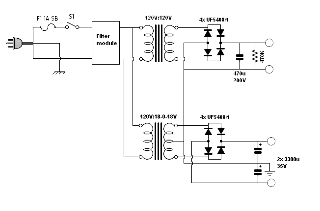
We begin with consideration of B+ needs. Isolation transformers are a dime a dozen, we don’t need a lot of voltage, so that is what we’ll use. There are many mansions in my father’s house; my favorite mansion is the old fashioned E-I core. One can buy these new for about $16 (the Triad World Series will give us ten times more current than we need, #VPS230110). Or, if you’re like me, you root around in the scrap box to find something. When you do, you’ll have the heart of a 160V (or so) supply, which gives the filtering and regulation plenty of room to maneuver while fighting the noise.
There are many religions regarding how the line voltage should be filtered. Much depends on your actual power source- mine seems to be relatively clean. Do please use a fuse, and make sure that the safety (earth) ground from the power line is securely tied to the chassis. You can kill three birds with one stone by using one of the Schurter power entry modules, which combine an IEC power connector, a fuse, and an RFI filter. A suitable unit is the 5200.0123.1, stocked by Mouser at about $21. If you don’t mind doing some extra metalwork, you can use the 5110.0133.1, which has the IEC receptacle and RFI filter, and then add a separate fuse-holder. An SPST on-off switch is optional. Terminal worrywarts will use a DPST and switch both sides of the line.
Following the transformer, we need rectification. Much bird is whipped debating the merits and demerits of various schemes. My take: use high speed diodes- they’re reasonably inexpensive and while I think their merits compared to old-fashioned 1N4007 types are minimal, their better performance certainly won’t hurt. The Vishay UF5408/1 is ridiculously over-rated at 3A/1000V, but costs about $0.32. Buy a pile and use them for your next twenty tube projects. Bypass the diodes, if that makes you happy. I didn’t bother- I’m paying for the following RC filter and by god I’m going to make it earn its keep. But a 0.1uF caps paralleled across each diode is quite customary.
What about tube rectifiers? I can grant their use for nostalgia reasons, but for me the trade-offs are too severe. High resistance, inefficiency, heat production, and unreliability are the demerits. The one strong point is the gradual warm-up, but it’s not much of an advantage here- the plate voltage is too low to induce cathode stripping and we’ve got the output solidly dethumped. Use a tube if you like, but there’s just no question that if the goal is solid and silent DC, silicon rules.
On to the filtration. We start off with a relatively honking 470u/200V cap, a common switching supply value. This isn’t an application where we need the ultimate in ESR or DA or whatever. We do, however, want that cap to be of good quality for the long haul, so my choice is a 105° C rated cap. If you’re like me, you’ll use a UCC KMH200VN471M25X30T2. That’s a mouthful of a part number, but Mouser sells them for about $2.50. If your wrist gets tired writing out that number, an equally good choice is the CDE 380LQ version, part # 471M200H022; it has a lower temperature rating (which is probably OK since there’s no real heat sources in the raw supply box), but has a very high ripple current rating. It’s up to you. Whichever we choose, before going any further, we’ve knocked our ripple down to less than a volt. A couple of RC filters and a regulator should have no problem scaling that back by another 80dB or so. We put in a 470K bleeder resistor for safety.
At this point, the raw B+ (about 160V) exits the power supply box in sufficient quantity to power two channels; mission accomplished. We’ll come back to the B+ line when we consider regulation and filtering options later.
Now, we have a heater, dethumper, and current source to power up. I used +/-12V supplies because I knew there would be a servo in my future. And even if there weren’t, the extra supply doesn’t represent any significant further investment in money or chassis space. Our current requirements are relatively modest- budget 365mA maximum for the tube heater (it will probably be 300mA, but worst case…), and another 5mA per channel for the current sources. Our servo, when it takes a bow, will only need another 5mA or so. So if we plan for a 500mA supply, we will have a comfortable margin.
I have separated out the filament and plate transformers. You can, in theory, use a transformer with both windings on the secondary, but there’s a penalty to pay- unless there’s an electrostatic shield, the interwinding capacitance will do a smashing job of coupling common mode noise onto the heater circuits. You can get a transformer with an interwinding shield and add common mode filtration; a suitable filter is shown in Morgan Jones’s “Valve Amplifiers,” figure 5.48, or you can improvise with an RF 1:1 transformer and a couple of 0.01uF caps. Hams with coffee cans full of 2.5mH chokes can use a pair of those to good effect. I didn’t use a common-mode filter in either of my units and saw no ill effect. But if you’re going to use a single transformer for high and low voltage or experience any noise coupling via the heater, spend the extra few dollars and put in a common mode filter. The transformer should be, at minimum, 30V CT (15-0-15) to allow the regulators a bit of room to breathe. 500mA current rating is more than enough. At the expense of a bit more regulator dissipation, a 36VCT unit was pressed into service; I used a scrapbox transformer, but suitable new units would include the Triad World Series VPP36560 (PC mount) or VPS36700 (chassis mount).
As with the high voltage supply, high speed diodes are a Good Trick, and a cheap one, too. If you’re a bug about power supply efficiency, Schottky rectifiers have a somewhat lower voltage drop than normal junction diodes. But, really, this is only half an amp we’re talking about. Since I was buying the UF5408/1s for the high voltage rail anyway, I just used the same thing for the heater supply. With a 3A continuous and150A surge rating, they’ll do fine.
This is a good time to consider reasonably big caps for the supply. A pair of low ESR 3300uF electrolytics will knock the ripple down to about 600mV. And they’ll be cheap. An exemplar is the Nichicon UPW1V332MMH, featuring 15 milliohms of ESR for under $3.00.
And that pretty much wraps up the raw supply.